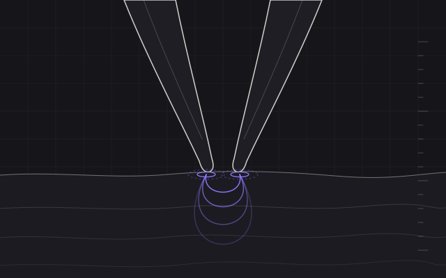
The physics of tissue impedance is well established. Measuring it cleanly at the tip of a surgical instrument is a different problem. Between the electronics and the tissue sit a cable, a metal surface, a thin layer of electrochemistry, whatever fluid happens to be on the tissue, and a contact patch that changes with every grip. Nearby, other equipment may be delivering far more energy than any sensing signal. This explainer takes each of these in turn as a general engineering problem. These factors define the engineering requirements for instrument-integrated sensing.
Where metal meets tissue
Metal conducts with electrons; tissue conducts with ions. Where they meet, current has to pass from one kind of carrier to the other, and that handover happens through electrochemistry at the surface. A thin layer of separated charge, the electrical double layer, forms at the boundary and behaves like a leaky capacitor in series with the tissue.
The impedance it adds is called electrode polarization impedance. It is largest at low frequencies, and it grows as the electrode area shrinks, which matters for small instrument tips. Herman Schwan, who studied the effect for decades, described electrode polarization as a major nuisance in measuring the electrical properties of tissues, particularly at low frequencies.Reference 1 In a study of needle electrodes in living tissue, readings from small electrodes were influenced by polarization at low frequencies.Reference 3
The interface is also nonlinear. Drive it with too large a signal and it stops behaving like a fixed impedance, generating harmonics that distort the result.Reference 1Reference 4 Keeping the test signal small, and checking that the response stays proportional to it, keeps the measurement in its linear range. The surface also changes with use: oxidation, adsorbed proteins and residue from earlier contact all alter the interface, so the same electrode can read differently at the end of a session than at the start.
Contact area and pressure
A measurement only describes tissue the current actually reaches, and how current gets there depends on contact. A small contact patch concentrates current, so the tissue right next to the contact dominates the reading and the interface impedance looms larger. A larger patch spreads current out and samples more tissue.
a Light contact through a fluid film
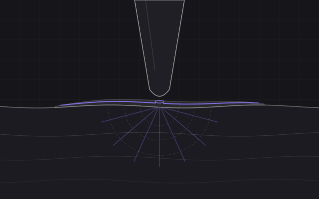
b Firm contact

- Current paths
- Lines of equal voltage around the contact
- Conductive fluid film
- Contact patch
- Applied pressure
Pressure matters as much as area. Pressing harder compresses tissue and pushes fluid out of the spaces between cells. In one study of esophageal, gastric and bladder tissue, resistivity readings rose consistently as probe pressure increased, by amounts larger than the tissue changes the investigators were trying to detect; they suggested that squeezing water from the extracellular space was the main cause.Reference 5 Another group found that a fixed loading weight and a fixed loading time were needed before spectra from excised tissue were reproducible enough to compare.Reference 6
A handheld surgical instrument does not apply a fixed, known force. Grip varies from surgeon to surgeon and from moment to moment. A practical system has to know, limit or correct for contact conditions, or rely on features of the signal that stay stable when contact changes. Establishing which of these approaches works, and when, is an engineering question in its own right.
Two electrodes or four
Textbooks describe two general ways to measure impedance.Reference 2
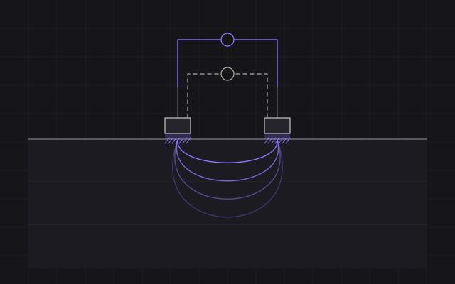
In a two-electrode measurement, the same pair of electrodes delivers the current and senses the voltage. It is simple and needs only two contacts, but everything in the current path is measured together: the tissue and both electrode interfaces. At low frequencies, where polarization impedance is large, the interfaces can dominate the result.
In a four-electrode measurement, one pair drives the current and a separate pair senses the voltage. The sensing electrodes draw almost no current, so their own interface impedance contributes very little and most of the electrode polarization drops out of the result. The costs are more contacts, more space and a less intuitive picture of which tissue the reading reflects: each region’s contribution depends on the geometry of all four electrodes, and some regions can even contribute with reversed sign.Reference 2 Four-terminal methods are widely used to measure tissue resistivity, with careful accounting of their own error sources.Reference 7
Neither arrangement is simply better. The right choice depends on the geometry available, the frequency range of interest and the question being asked.
a Two-electrode
b Four-electrode
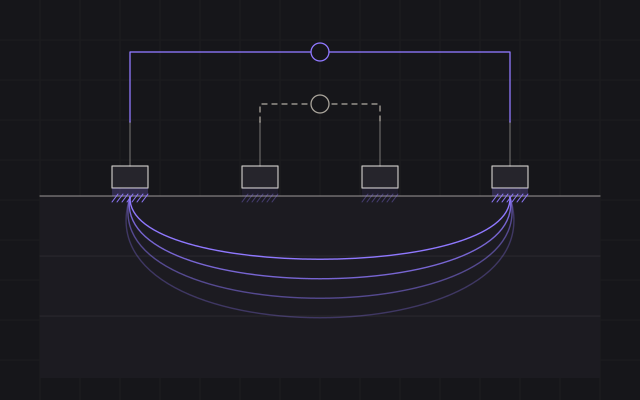
- Current paths and the drive loop
- Voltage-sensing loop
- Electrode–tissue interface; faint where little current crosses it
Calibration: knowing what the instrument adds
Before a reading can describe tissue, the instrument’s own contribution has to be characterized. Standard practice uses three kinds of check.
- Open. Nothing connected, which reveals stray capacitance and leakage in the measurement path.
- Short. The measuring contacts joined directly together, which reveals the resistance and inductance of leads and connections.
- Known loads. References with precisely known impedance, including networks built to imitate a tissue-like response, and conductive solutions of known conductivity.
From these checks the instrument’s contribution can be characterized and corrected within the calibration model, ideally with the calibration reference plane at the electrodes, where tissue will be measured, rather than at the measurement electronics. Conductive solutions also set the cell constant that converts a measured impedance into a material property. One detailed error analysis of tissue resistivity measurement traced contributions from the reference solution, the probe constant, differences in current level between calibration and measurement, and electrode spacing and surface condition.Reference 7 Every step that turns a raw reading into a tissue property carries its own uncertainty.
Drift and repeatability
Electronics drift with temperature and time. Electrodes change with use. Tissue changes after excision. Interpretation depends on readings that repeat.
Repeatability tracks variation under the same measurement conditions over a short period. Broader evaluations examine variation across sessions, operators, instruments and sites. Both are measured by returning to the same references and specimens and recording how far readings move. Reference checks at the start and end of a session reveal drift.
Cables and stray paths
Cables are not neutral. Every conductor has capacitance to its neighbors and to ground, and that stray capacitance offers current an alternative path that matters more as frequency rises. Leads also add resistance and inductance. Move a cable and its stray capacitance changes, which can shift a reading with no change in the tissue at all.
The general remedies are well known: short leads, shielding, fixed cable routing and calibration that includes the cable. Some groups model the parasitic effects of cables and amplifiers explicitly and remove them from the measured spectrum.Reference 8 For an instrument held in a surgeon’s hand and moved constantly, keeping these effects stable is part of the design problem from the start.
Wet surgical fields
The surgical field is rarely dry. Blood, irrigation saline and tissue fluid are good conductors, often better than the tissue beneath them. A film of fluid around the contacts can carry current along the surface instead of through the tissue, so the instrument ends up measuring the film. The film’s thickness changes from moment to moment, and the temperature of irrigation fluid adds another variable. Exposed tissue can also dry out, which shifts readings the other way.
A measurement intended for surgery has to recognize when a reading is dominated by surface fluid rather than tissue, and treat that reading as uninformative instead of passing it on.
Sharing the field with energized instruments
Electrosurgery uses high-frequency alternating current to cut and coagulate tissue.Reference 9 The power involved is many orders of magnitude greater than a sensing signal. Any sensing system that shares the field with energized instruments has to coexist with them in four ways.
- Survive. Sensing electronics must tolerate energy applied through the same instrument or one nearby without damage.
- Recognize. Energy delivery can overwhelm sensing signals. The measurement design must establish when valid readings are available and exclude readings affected by interference.
- Reinterpret. Heating and coagulation change tissue’s electrical properties, so a reading taken just after energy delivery describes altered tissue.
- Stay safe. Sensing current must stay within the limits that medical electrical safety standards place on current passed through a patient, and must not disturb other equipment.
Development priorities
Each factor above informs the order of work. Reference loads come before tissue. Controlled contact comes before handheld use. Repeated measurements come before comparisons. The wet, energized surgical field is part of the design environment from the beginning. These priorities guide the development sequence.
This educational overview describes general measurement methods and engineering priorities.
References
Schwan HP. Linear and nonlinear electrode polarization and biological materials. Annals of Biomedical Engineering. 1992;20(3):269–288. doi:10.1007/BF02368531 · PMID 1443824
Grimnes S, Martinsen ØG. Bioimpedance and Bioelectricity Basics. 3rd ed. Academic Press; 2015. ISBN 978-0-12-411470-8.
Kalvøy H, Frich L, Grimnes S, Martinsen ØG, Hol PK, Stubhaug A. Impedance-based tissue discrimination for needle guidance. Physiological Measurement. 2009;30(2):129–140. doi:10.1088/0967-3334/30/2/002 · PMID 19136732
Moussavi M, Schwan HP, Sun HH. Harmonic distortion caused by electrode polarisation. Medical & Biological Engineering & Computing. 1994;32(2):121–125. doi:10.1007/BF02518907 · PMID 8022206
González-Correa CA, Brown BH, Smallwood RH, Walker DC, Bardhan KD. Electrical bioimpedance readings increase with higher pressure applied to the measuring probe. Physiological Measurement. 2005;26(2):S39–S47. doi:10.1088/0967-3334/26/2/004 · PMID 15798245
Emran S, Lappalainen R, Kullaa AM, Myllymaa S. Concentric ring probe for bioimpedance spectroscopic measurements: design and ex vivo feasibility testing on pork oral tissues. Sensors. 2018;18(10):3378. doi:10.3390/s18103378 · PMID 30308986
Tsai JZ, Will JA, Hubbard-Van Stelle S, et al. Error analysis of tissue resistivity measurement. IEEE Transactions on Biomedical Engineering. 2002;49(5):484–494. doi:10.1109/10.995687 · PMID 12002180
Dutra D, Bertemes-Filho P. Extracting parasite effects of electrical bioimpedance measurements. Journal of Electrical Bioimpedance. 2018;9(1):115–122. doi:10.2478/joeb-2018-0016 · PMID 33584927
Massarweh NN, Cosgriff N, Slakey DP. Electrosurgery: history, principles, and current and future uses. Journal of the American College of Surgeons. 2006;202(3):520–530. doi:10.1016/j.jamcollsurg.2005.11.017 · PMID 16500257

